24 hours services in your doorstep. Call - +91 6291668065
24 hours services in your doorstep. Call - +91 6291668065
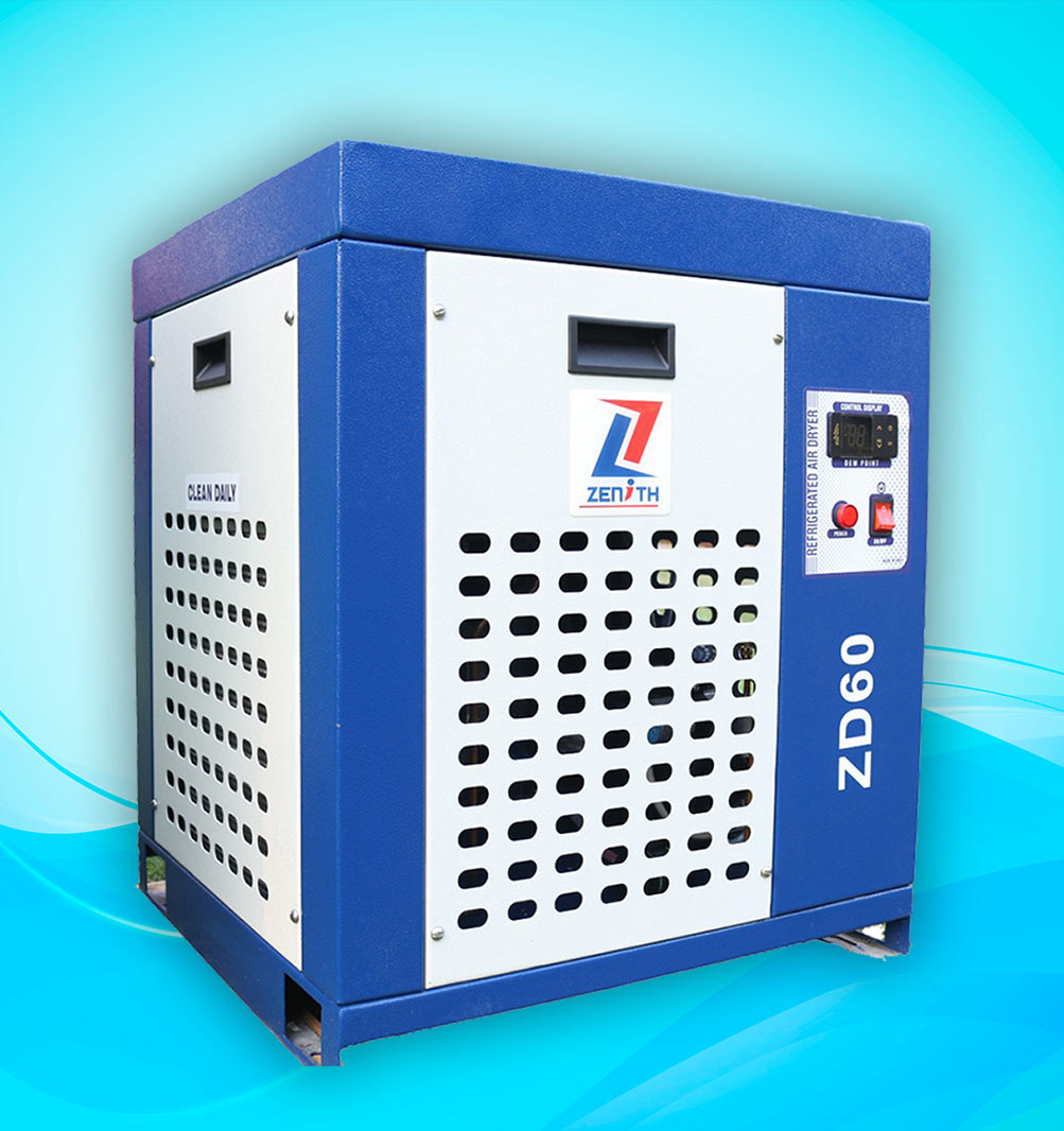
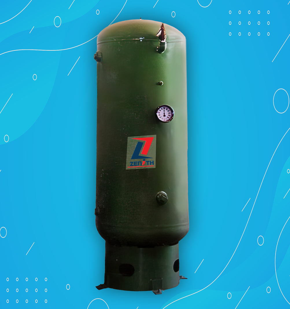
The Compressed air leaving a compressor contains considerable quantities of water vapor. If the untreated air is supplied into the distribution lines, the moisture would condense to liquid water as it gets cooled. Condensed water is a major cause of downtime in compressed air systems. Water causes rust, pitting, blockages and freeze ups, which results in component failure and product rejection. The only way to prevent condensation of water in air lines is to lower the dew point of the air in the system. It is less expensive to own and operate an air dryer than to live with the problems it can prevent.
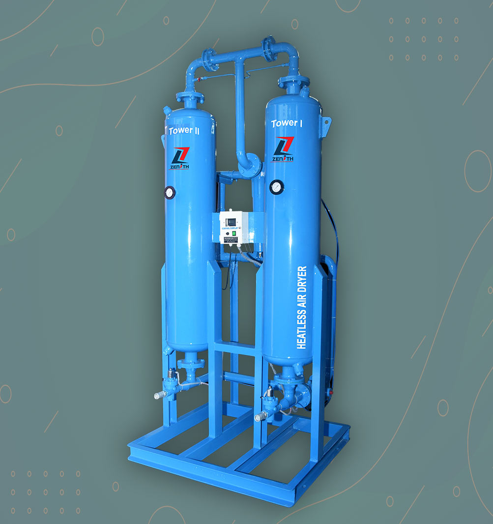
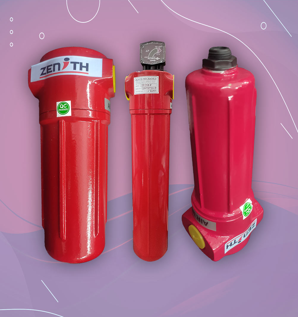
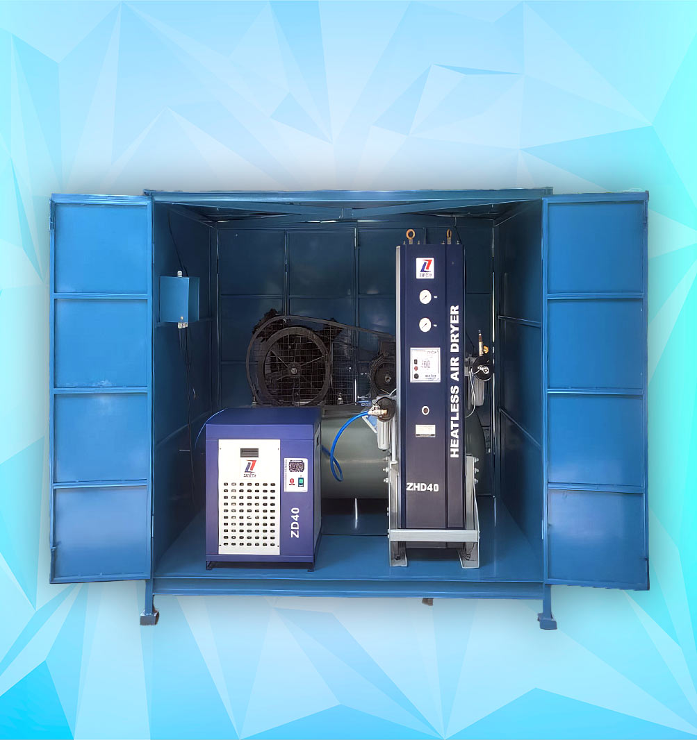
Coalescing filters of 5 micron and 0.01 micron removes bulk moisture and liquid oil from the compressed air. This pre-treated air diffuses to the bottom of the adsorber (T1) and passes through the desiccant bed. This desiccant bed adsorbs moisture and dries the air. Dry air leaves the adsorber (T1) and passes through 1 micron dust filter. Thus dry, filtered compressed air is available to the application.
This desiccant can adsorb only certain quantity of moisture and will reach equilibrium after certain time. It can no longer dries the air to the required dew point and should be regenerated to keep the process continuous. To generate the first adsorber (T1), some partial quantity of dry air coming out of second adsorber (T2) is diverted to first adsorber (T1). This Dry air expands to atmospheric pressure and become subsaturated. This subsaturated dry air purges out all moisture from the first adsorber (T1) and makes it ready for next adsorption.
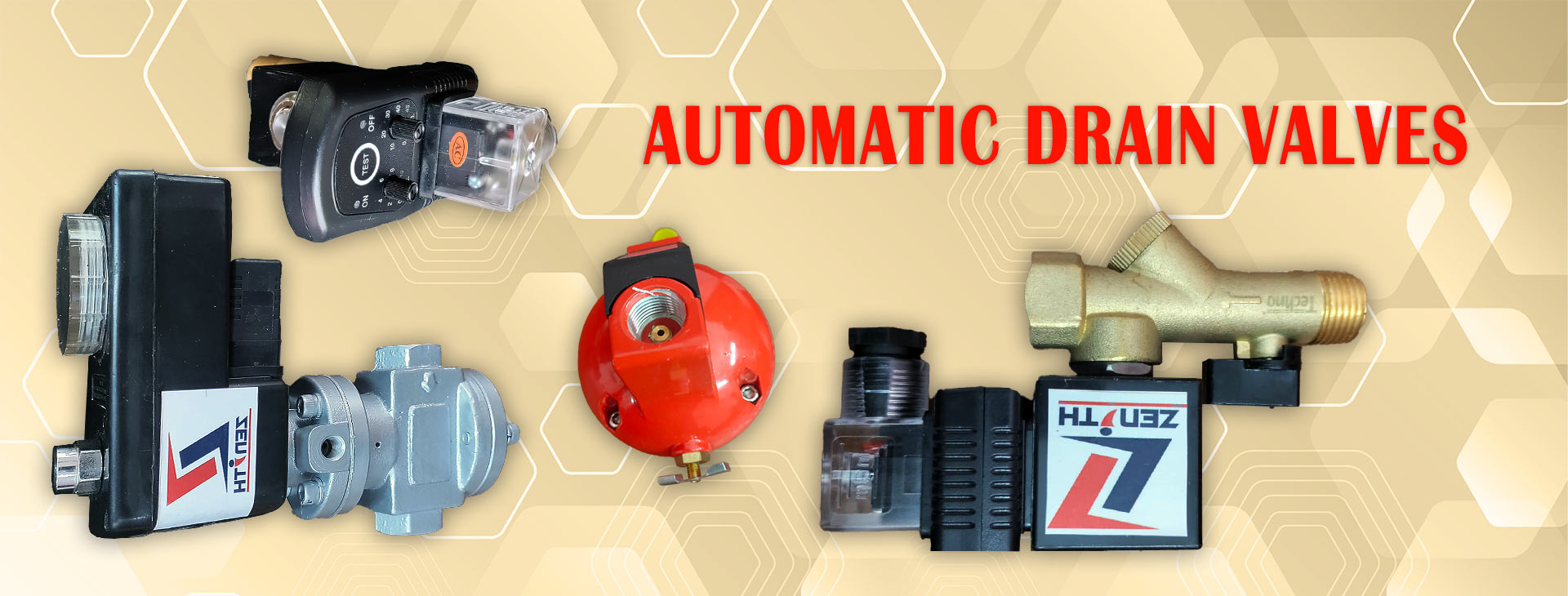
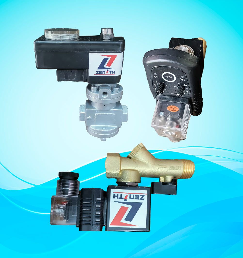
Air flow is diverted to adsorber column alternatively by valves and controller.
Product Model | FAD, cfm | In/Out | Weight (kg) |
ZHD 40 | 40 | ½’’ | 210 |
ZHD 60 | 60 | ¾’’ | 240 |
ZHD 80 | 80 | 1’’ | 290 |
ZHD 100 | 100 | 1’’ | 320 |
ZHD 125 | 125 | 1’’ | 370 |
ZHD 150 | 150 | 1-1/2’’ | 415 |
ZHD 200 | 200 | 1-1/2’’ | 450 |
ZHD 250 | 250 | 1-1/2’’ | 520 |
ZHD 300 | 300 | 1-1/2’’ | 640 |
ZHD 350 | 350 | 2’’ | 700 |
ZHD 400 | 400 | 2’’ | 740 |
ZHD 500 | 500 | 2’’ | 1100 |
Energy management controller to minimize purge loss
Large dessicant beds for consistent dew point
Outlet air quality according to ISO 8573-1, 7.3, Table 3, Class 3 & 2.
Capacity
Inlet Air Temp
Working Pressure
Dew Point Temperature
Dew Point
: 10 to 10,000 cfm
: 5 to 450C
: 6 to 15 bar g
: – 400c Atmospheric
(–700c Optiional) Pressure
: – 200c to – 400c